
© 2023 DE KOKER Guillaume.
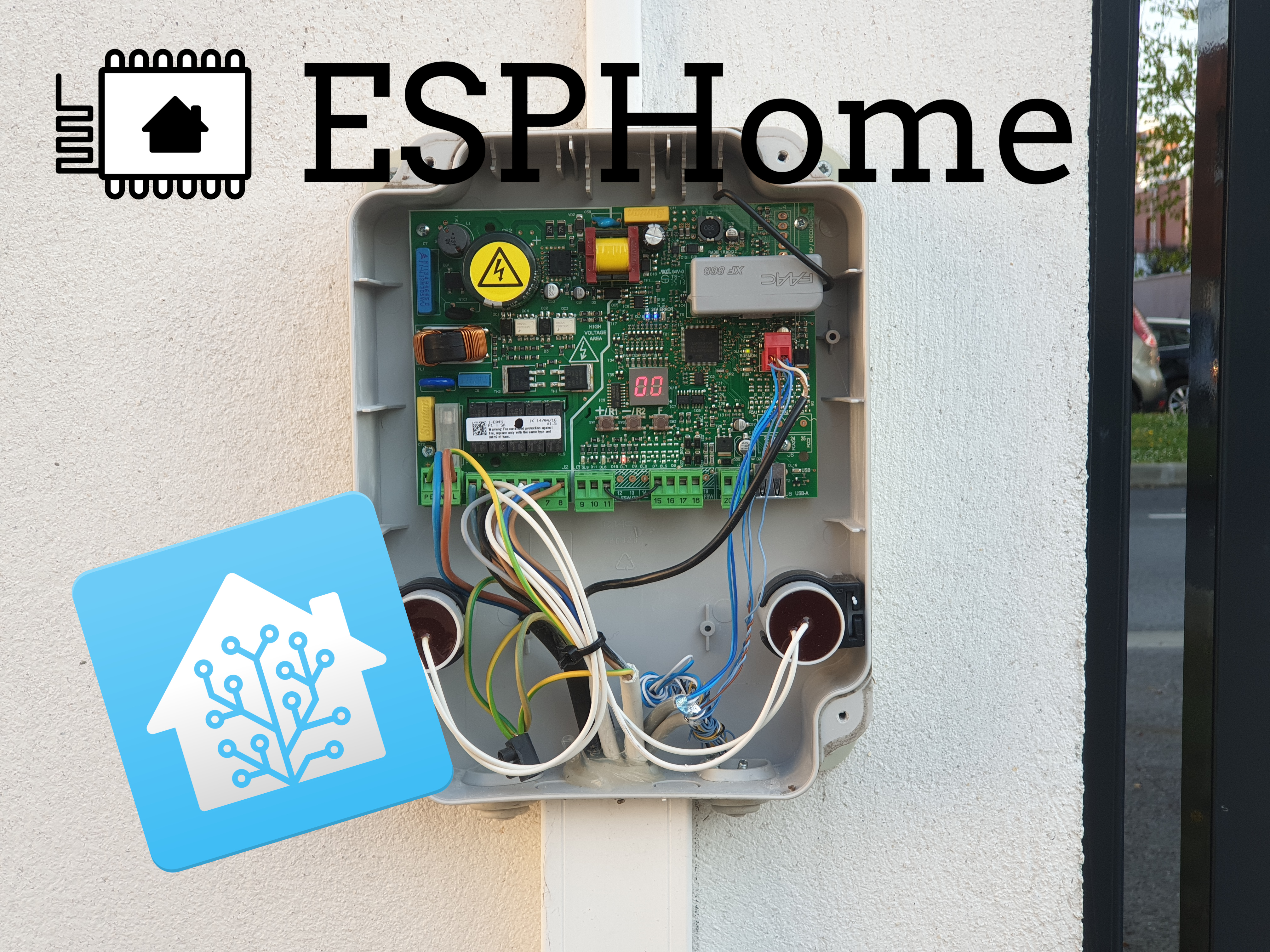
A couple of years ago, I made this DIY add-on to my gate controller to manage it through Home Assistant. It’s Wi-Fi enabled, can warn me if it’s stuck, allows me to check its state, and control it reliably through Home Assistant, and didn’t cost much more than 15€.
Because the gate controller was provided with the house, I didn’t want to replace or damage it in any way, so I needed to make something that works in harmony with what I had.
Working with what we have
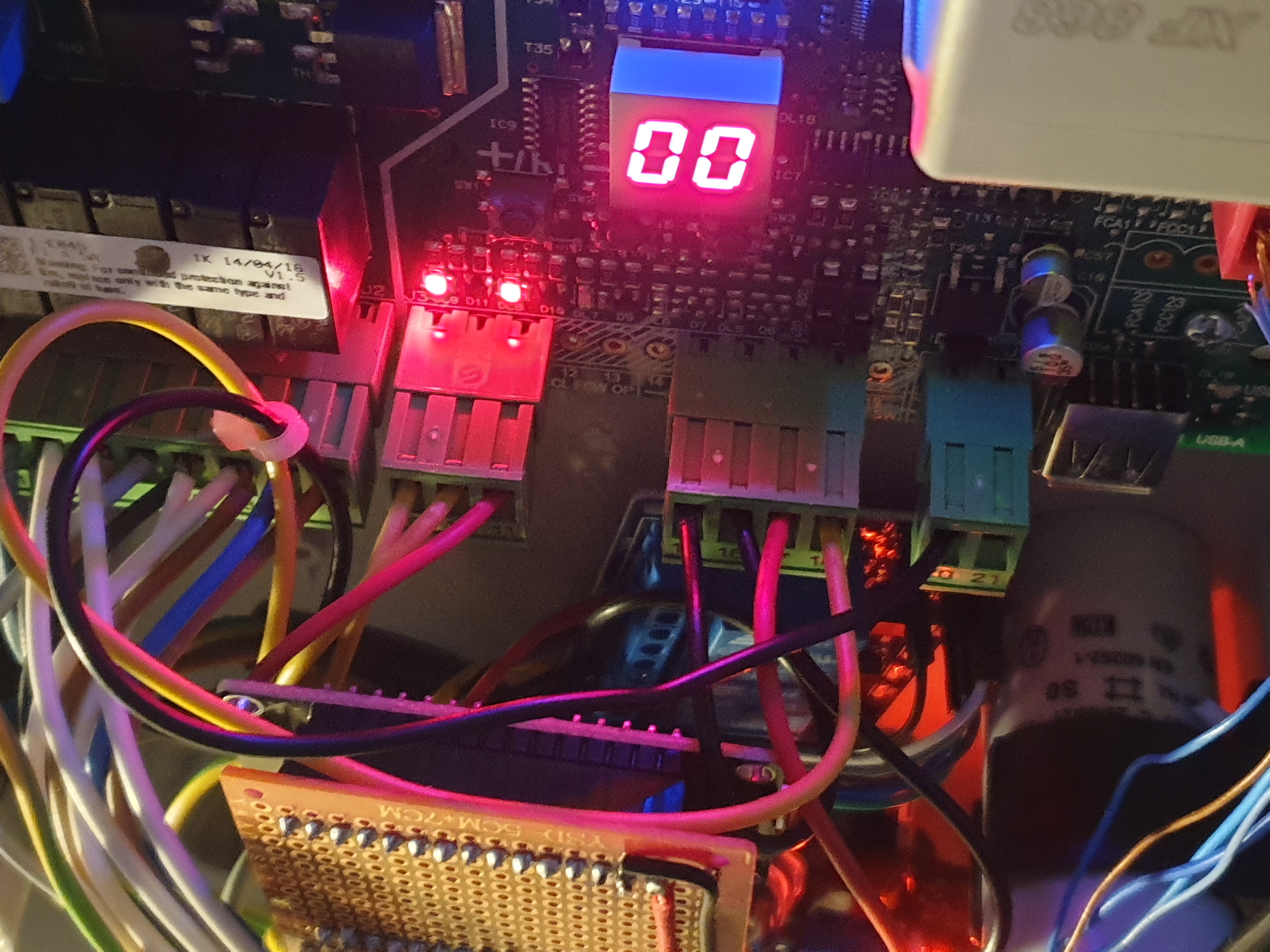
The first order of business was to see what we could work with. I opened the control box and checked what the controller was.
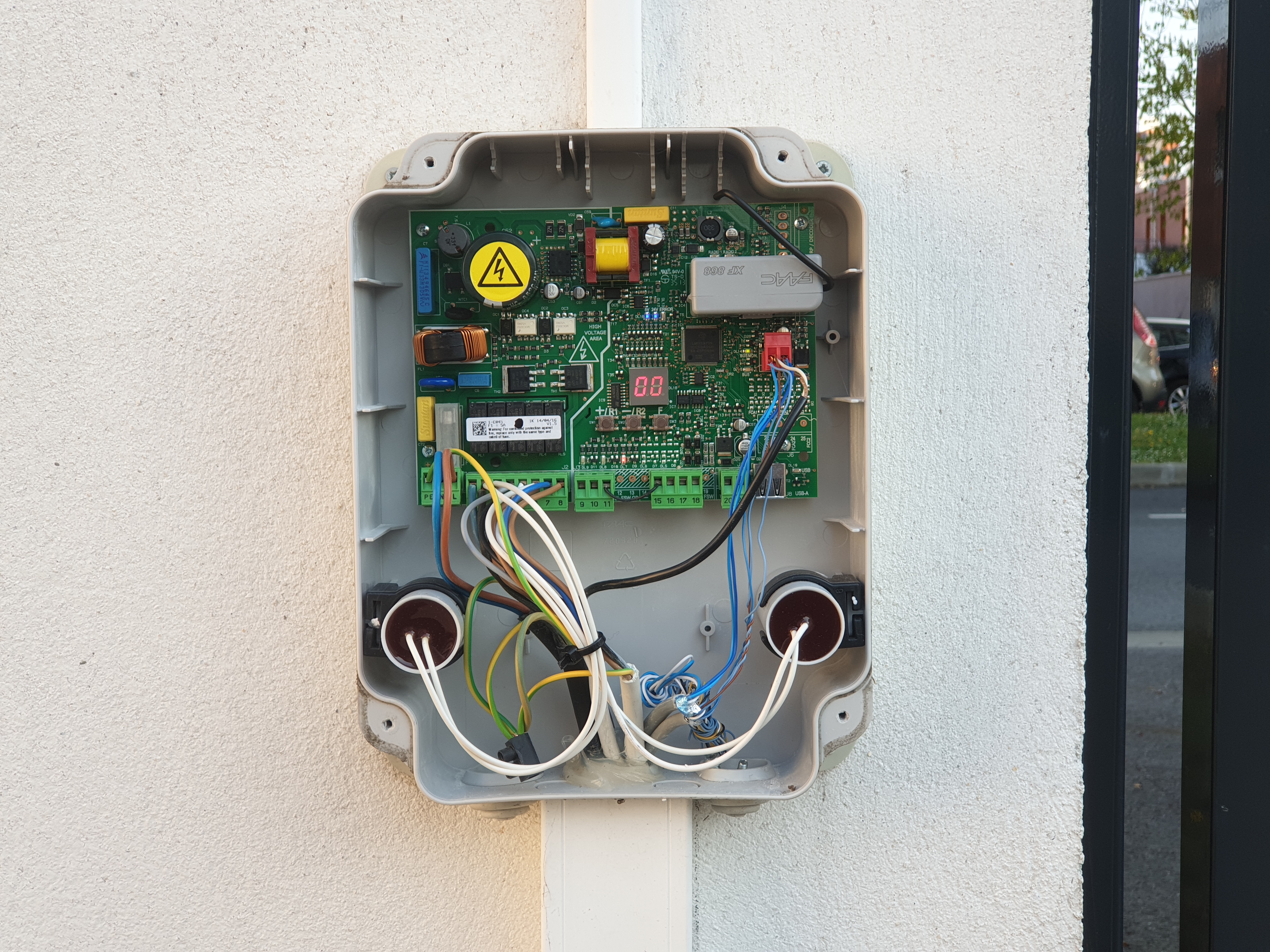
This is a FAAC E045 controller (it was written somewhere on the PCB). I pulled the datasheets and looked at the red terminal block with everything shoved in it, and the empty green terminal block.
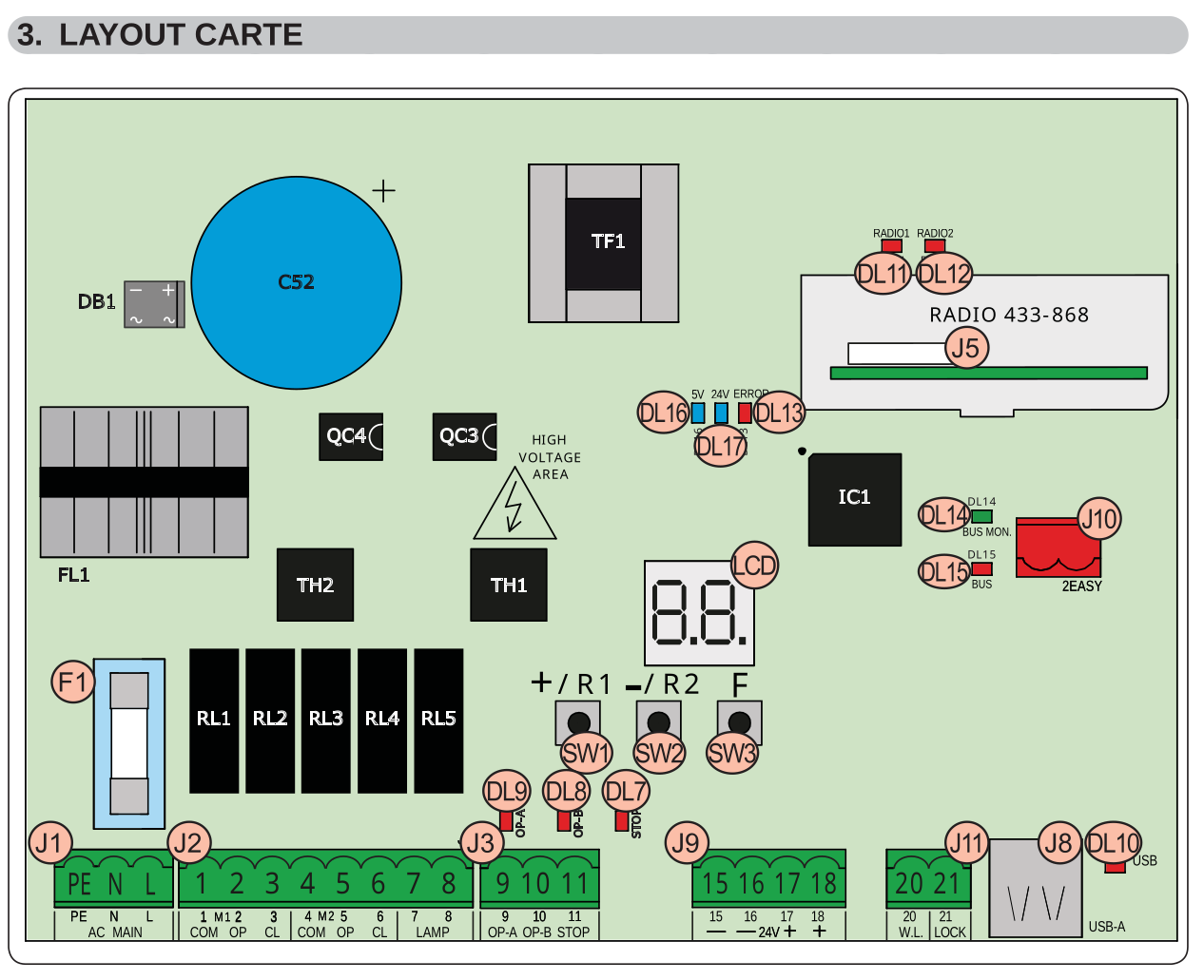
This is what I noted:
- J10 is a bus port for the Bus-2easy protocol; it looks like it can do everything I could want except I didn’t want to implement a custom bus protocol…
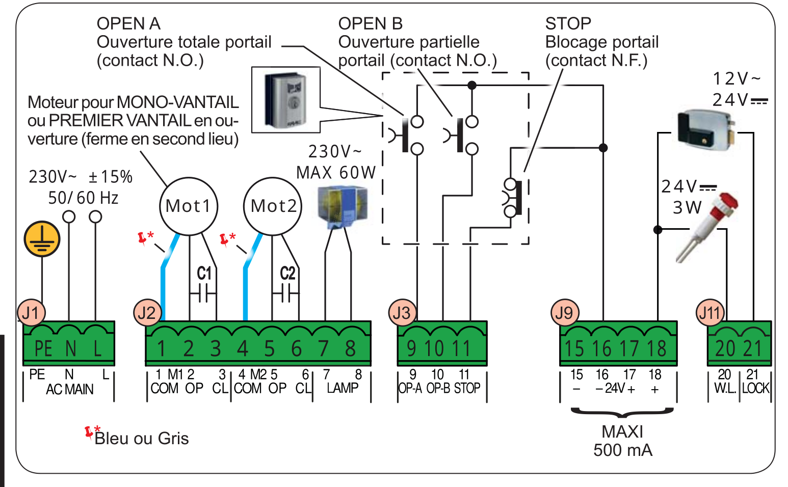
- Pulling J3-9 to ground would open the gate.
- Pulling J3-10 to ground would open only one side of the gate to let people get in.
- Opening J3-11 would stop the current action, explaining why it was hard-wired.
- I can pull up to 500mA at 24v AC from the J9 connectors to power my controller.
- J11-20 is a status light that you usually put inside your house to see if you forgot to close the gate. I can use that to get my status.
To recap, what I need is a 24v powered controller with 3 relays and a way to read the unused indicator light status. I tested that light status and found it would do 3 things:
- It’s OFF when the gate is fully closed.
- It’s ON as soon as the gate is open, even a little bit.
- It will blink when the gate is closing.
Given this, I know that I can get 3 states out of it, Open, Closing, and Closed. I can’t get Opening.
Creating a controller
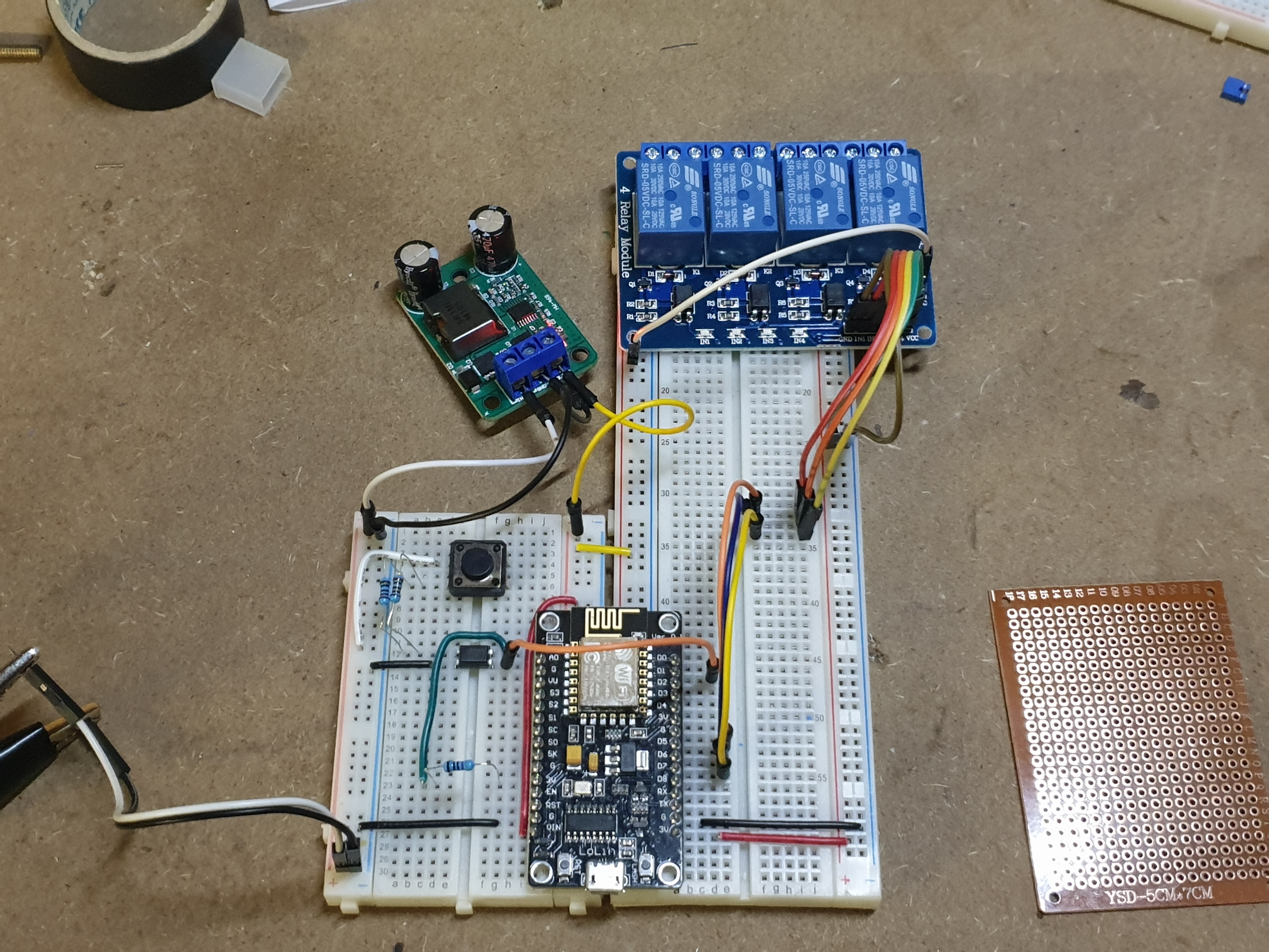
With all the information I gathered, I started to plan my controller. I knew I wanted it to run on 24V, and luckily I had some 24-12v to 5V 5A Buc converter laying around from a previous project. I also knew I would use an ESP8266 because I ordered a couple and it was compatible with ESPHome. To control the gate, I ordered a 5V 4 relay board that you could control with 3.3v from the ESP directly. You just have to remove a jumper and provide 5V to the relay. Finally, to get the 24V input from the indicator light, I didn’t want to work too hard cleaning it and making sure it’s at a safe level for the 3.3V logic input of the controller. So, I’m using an optocoupler that can take 24V in.
I started working and made some mistakes along the road. My days of electronic classes are far behind me … well not far but far enough … and it took me several revisions to get it right. Unless specified, pictures are not of the final working product.
- Overcomplicated design because I wanted to use a pull-down for the optocoupler output when the ESP8266 had a perfectly working internal pull-up
- Grossly miscalculating the needed current for the optocoupler input and with that, the resistor I needed (burnt electronics, a smell you never forget)
Armed with this knowledge (thanks to Davorin from the ESPHome Discord, by the way), I started to make a “PCB” layout.
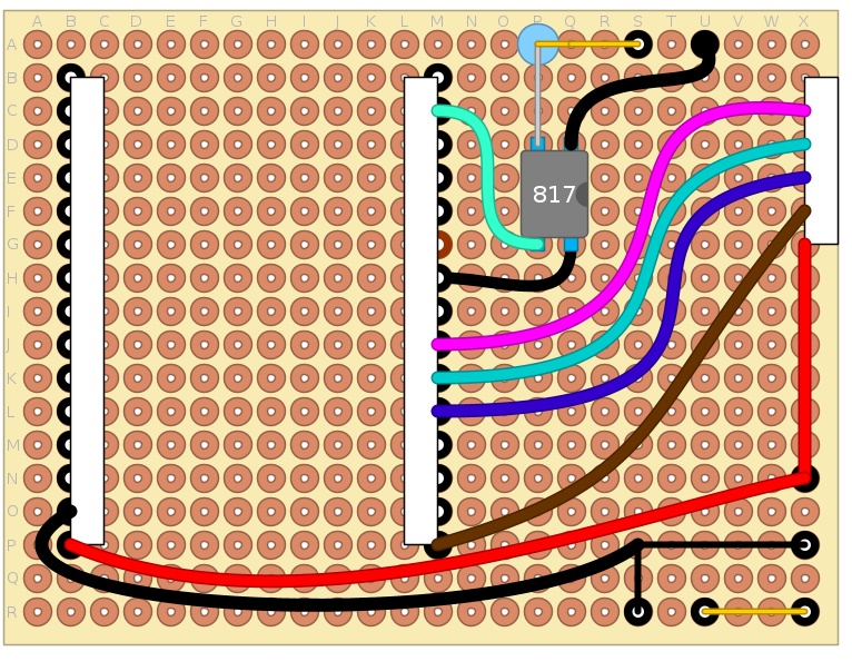
- In A-S to A-U, you have the input terminal block for the indicator light. The VCC side goes through a 10K resistor, in the PC817 optocoupler and back out to ground.
- The other side of the optocoupler is connected to a ground pin on the ESP and the D1 pin, which is GPIO5 (actually, I ended up soldering it to D2 just under it, which is GPIO4, because I can’t count … but that’s not important).
I should have used D0, which is a
wakepin in hindsight. This way, I could have put the ESP to sleep and saved some power. - An IO connector from B-X to G-X is dedicated to the relay board:
- B-X is ground (not shown).
- G-X is 5V from the buck converter.
- C-X to E-X are the 3 relay control signals connected to D6 (GPIO12), D7 (GPIO13), and D8 (GPIO15).
- F-X is 3.3V from the internal step-down converter of the ESP8266 I’m using (LoLin V3 from NodeMCU).
- From N-X to R-X is a 3-wire terminal block that goes to the buck converter.
- Finally, in R-S to R-U is the 24V VCC input.
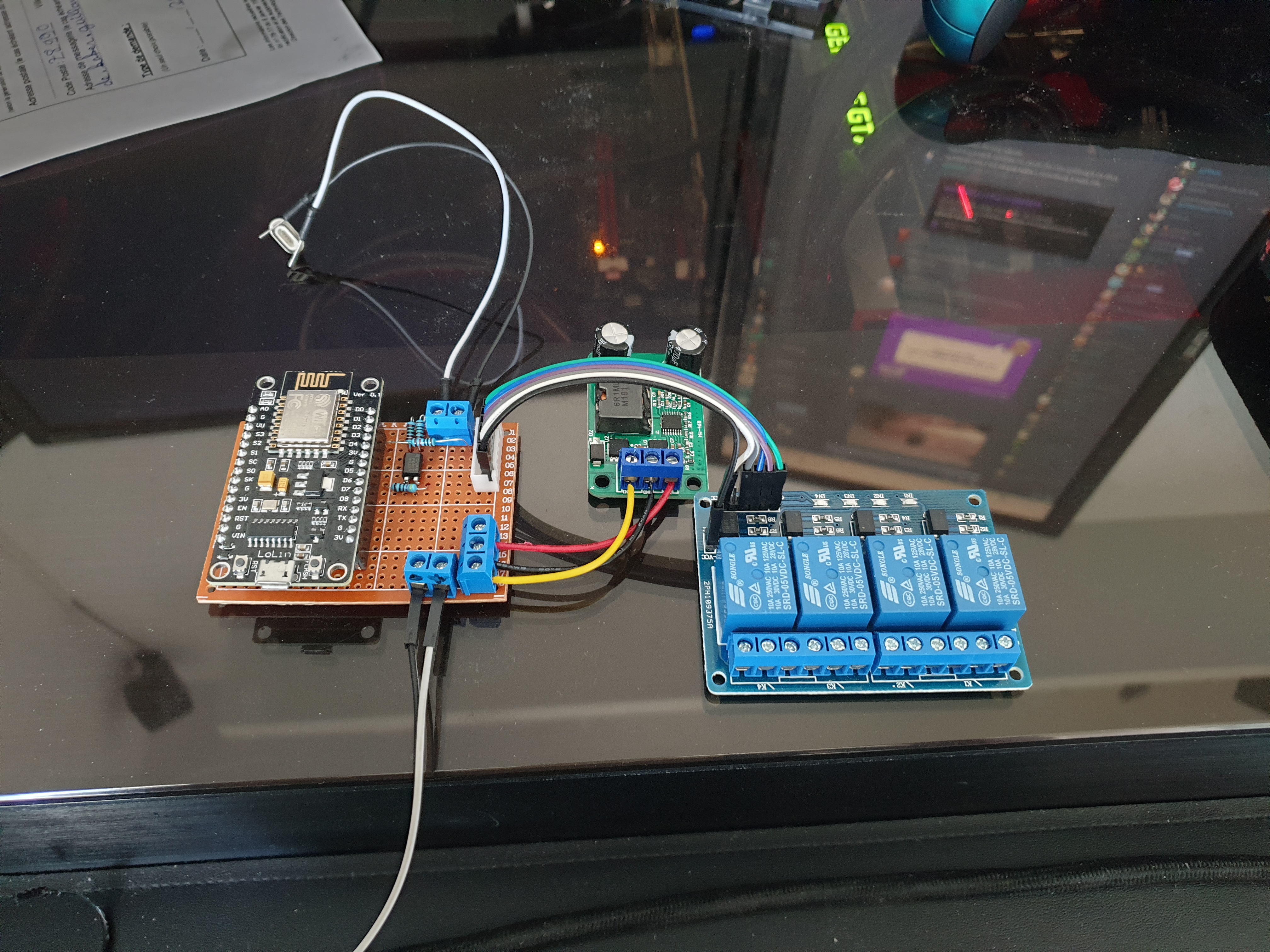
All soldered up, this is how the final version looks (please forgive the very bad soldering job of 2021 me):
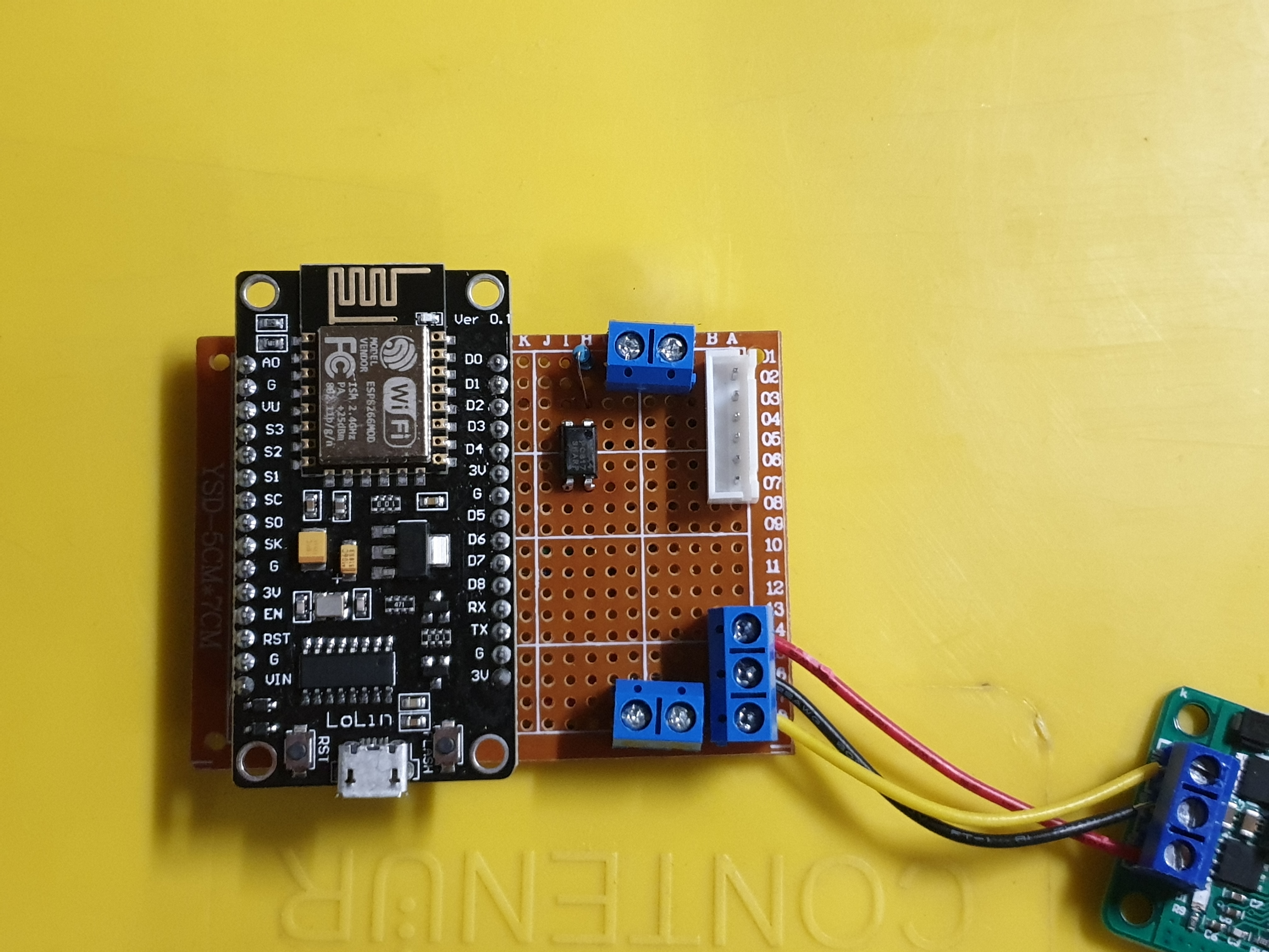
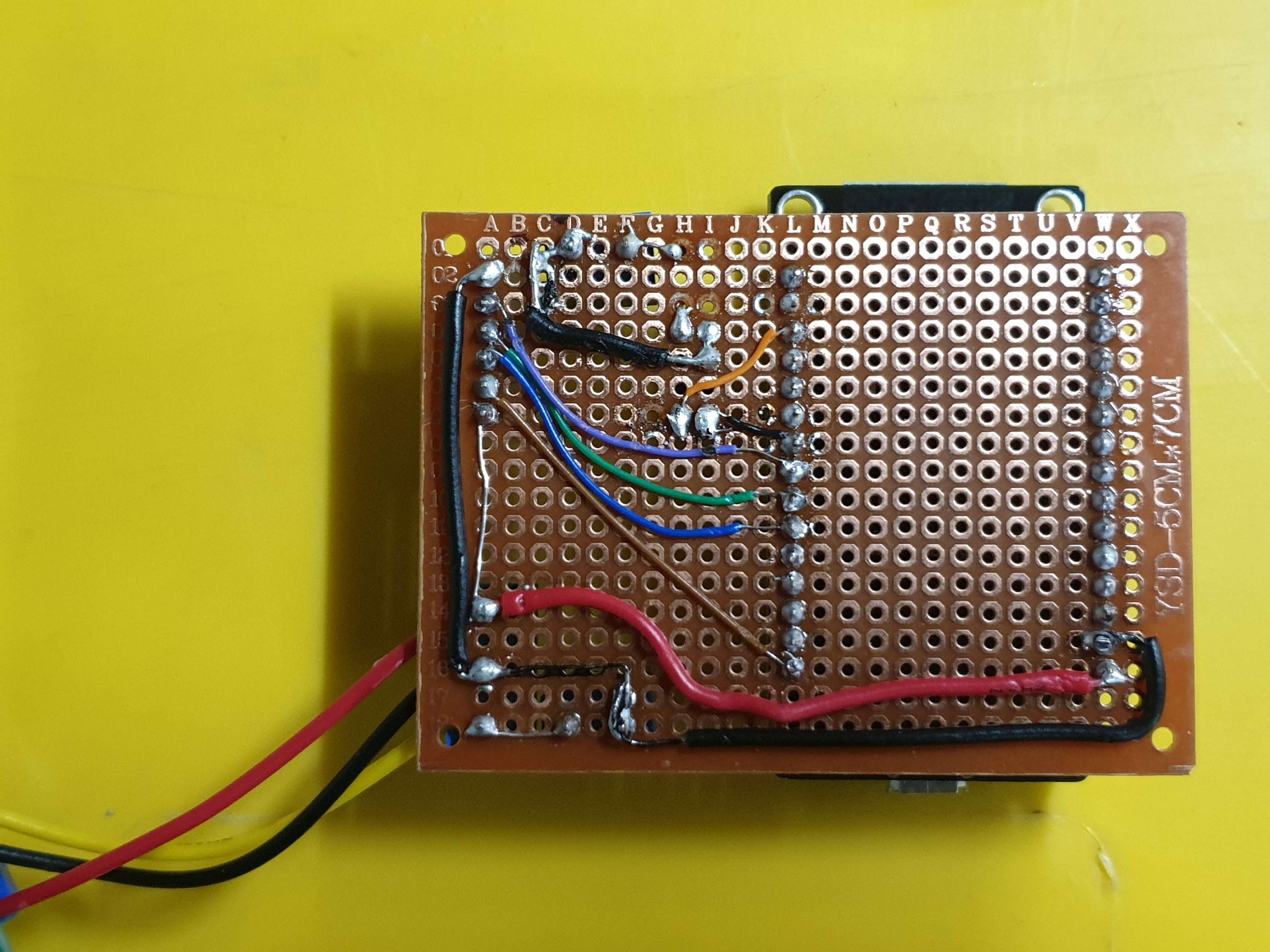
Very bare and very simple. I then wired everything to test and program it.
Time to “Code”!
My last project with an ESP was an accent lighting I made for visual notification … and at the time, I did it all in C++ in the Arduino IDE…
So compared to it, ESPHome is WAAAAYYYY easier.Today i installed my entrance light with led notification !
— Vaarlion (@vaarlion) May 17, 2020
Thanks to @home_assistant, i now have some visual feedback about the alarms state, which bin to put out, or what ever i want ! pic.twitter.com/Zj1TLN2q65
You can find the code on this gist, I will have it updated soon to use the latest Home-assistant integration and to replace the API password with the new mandatory Encryption key.
The main part hasn’t changed. You want:
- A sensor for the light indicator GPIO pin. I’m using a
duty_cycleto detect when the light pulses:sensor: - platform: duty_cycle id: input_state update_interval: 1s pin: number: D2 mode: input_pullup inverted: true - Two binary sensors, one for the open-close status and one for when the gate is closing:
binary_sensor: - platform: template name: "Gate State" id: state_open filters: - delayed_off: 1200ms lambda: |- if (id(input_state).state > 0) { // gate is open. return true; } else { // gate is close. return false; } - platform: template name: "Gate closing" id: state_closing filters: - delayed_on_off: 1200ms lambda: |- if ( id(input_state).state > 1 and id(input_state).state < 99) { // gate is closing. return true; } else { // gate is idle. return false; } - The three output relays with a template to generate a small pulse:
output: - platform: gpio pin: D5 id: relay1 inverted: True - platform: gpio pin: D6 id: relay2 inverted: True - platform: gpio pin: D7 id: relay3 inverted: True # Pulse generator - platform: template type: binary id: open_close_portal_full write_action: - output.turn_on: relay2 - delay: 500ms - output.turn_off: relay2 - platform: template type: binary id: open_close_portal_half write_action: - output.turn_on: relay1 - delay: 500ms - output.turn_off: relay1 - platform: template type: binary id: stop_portal write_action: - output.turn_on: relay3 - delay: 500ms - output.turn_off: relay3 - And finally, the cover, which is the object type for gates, rolling shutters, stuff that open and close:
cover:
- platform: template
    name: "Portal"
    device_class: gate
    lambda: |-
      if (id(state_open).state) {
        return COVER_OPEN;
      } else {
        return COVER_CLOSED;
      }
    open_action:
    - output.turn_on: open_close_portal_full
    close_action:
    - output.turn_on: open_close_portal_full
    stop_action:
    - output.turn_on: stop_portal
With this and the ESPHome documentation, you should be able to compile a working code in no time!
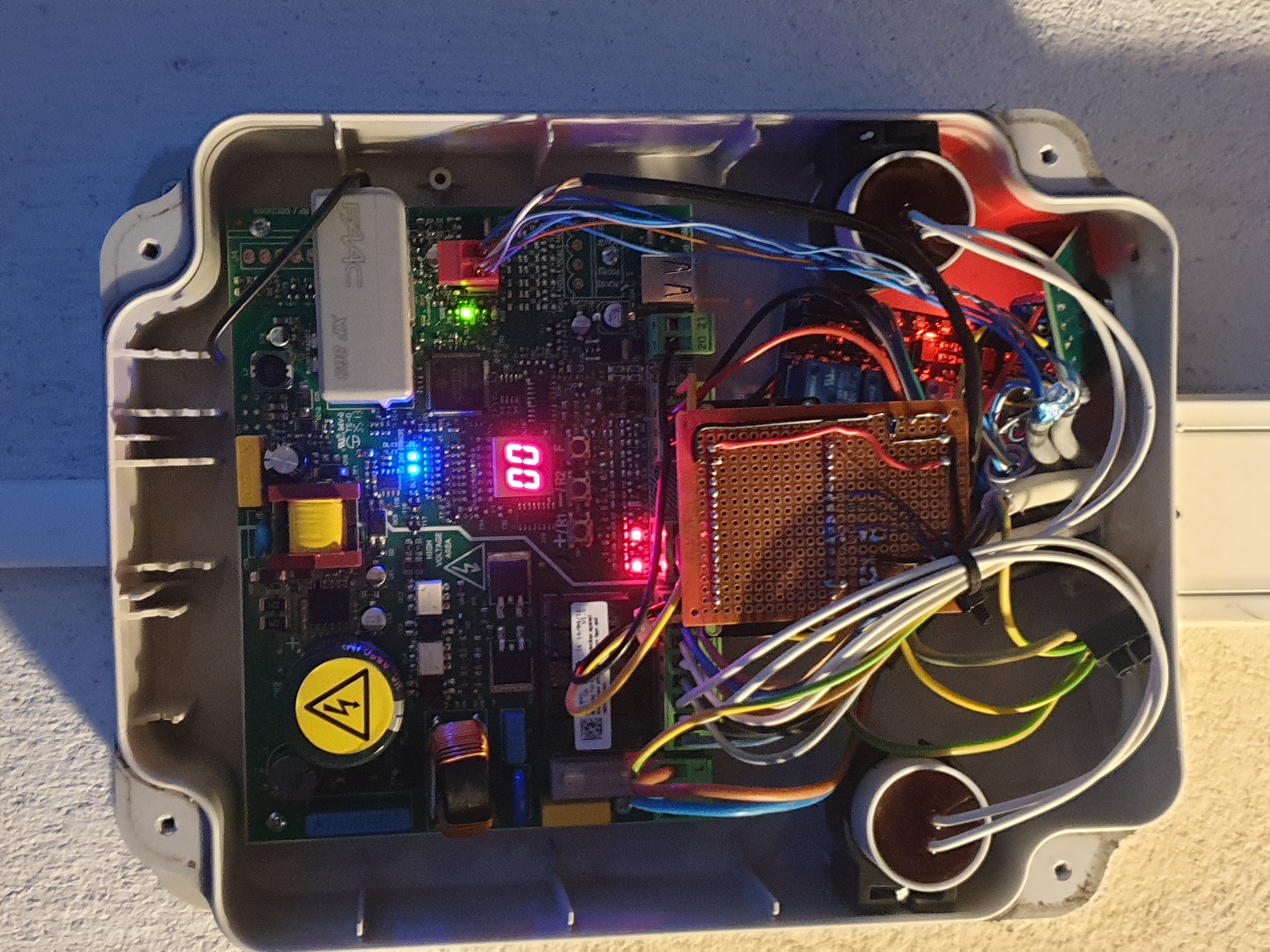
Let’s carefully install it
Yeah … no … I had to make it fit somehow … The terminal block unlocks so I could easily secure my cable in, I wired it all up, making sure to use the normally closed part of the stop relay (remember it stops as soon as it’s open) and shoved it in the box.
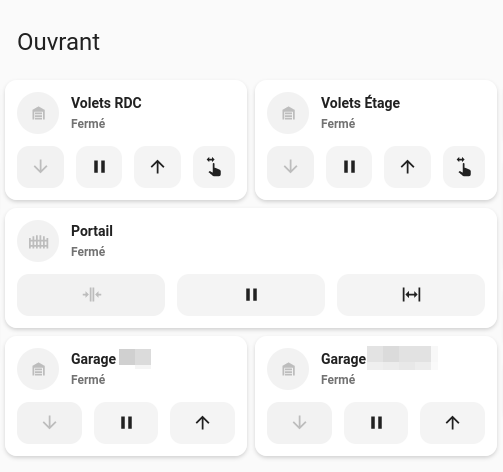
Home Assistant
The good thing with ESPHome is that if you made your device configuration correctly, it will show up on its own in Home Assistant. But until now I made a dumb device. The open and close button both trigger the same open_close_portal_full function … not very useful.
To fix this, I made a couple of Home Assistant scripts that you can find in this gist as a package.
I’m creating a gate_positioned gate that have additional logic to reach the requested status from the user. After a couple of years, it works very well and I’ve personally added a TTS warning when the gate couldn’t close correctly.
Wrap-up
It was honestly pretty easy, thanks in no small part to ESPHome. If you have a classical gate controller, I recommend that you check the model and the doc about it, you might be surprised to find that you already have dedicated Open and Close contacts that make it way easier.
It’s also a good first project because most of it is plug and play, a couple of relays and an input, you could get all of it in I2C format and not even think about hardware.